Senior Design Project
SAE Aero Design Competition
Mechanical Engineer-Fuselage Design
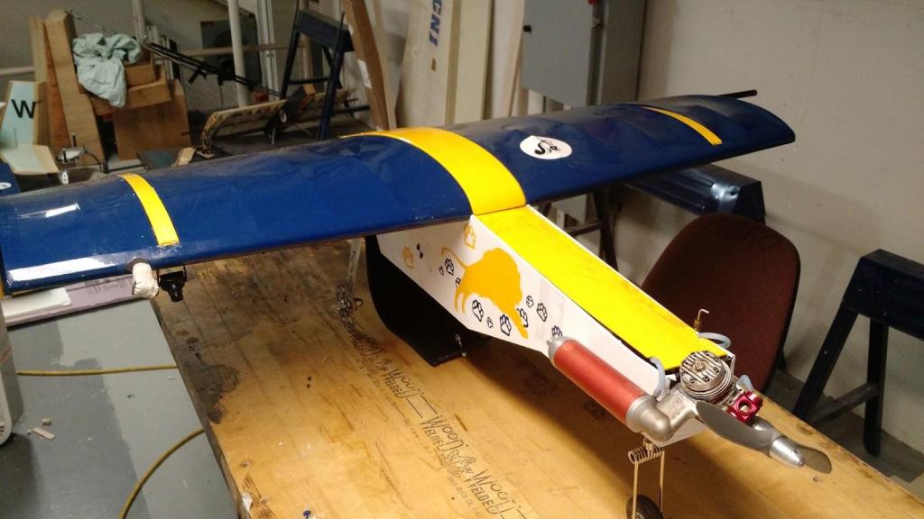
The focus of my Senior Design Project was the design and development of an Aircraft for the delivery of humanitarian aid. This humanitarian aid was represented with 2lb payloads, both housed within the body to carry and the payload bay to be dropped. The portion being released needed to be done from a minimum of 100ft above ground level aimed at a target using on board cameras and electronics. The design of the airplane was broken down with the portion I designed being the Fuselage, the main body of the plane. This houses electronics, fuel, payload, ballast and landing equipment. This also typically includes the engine depending on the configuration, but is the case for this design.
Design Requirements And Considerations
The design of the Fuselage involved three primary requirements. The first requirement was connecting lift and stability systems, the wings and tail. The next major requirement is adjusting the center of gravity relative to the center of lift to make the system stable. The final requirement is to integrate different subsystems, including the fuel system/engine; telemetry and radio control electronics; landing gear; and ballast and payload. The major criteria for improving design and performance include minimizing cost, minimizing weight, minimizing drag, and keeping manufacturability reasonable.
The design process for the fuselage was an iterative approach. This began with dividing the structure into four distinct zones. The first zone is the extended front end which mounts the engine and landing gear; and houses the ballast, fuel, and electronics. The second zone was the payload area. The third zone was the attachment area for the wings. The final zone included the mounting location for the rear landing gear, radio transmitter/receiver, and emergency shut off. We also looked to minimize overall cross section to adjust the slenderness ratio and minimize drag.

Material Choice
The choice of material for the focused on two main objectives: maintaining a large strength to weight ratio, and minimizing cost. Material options spanned three primary choices: metal, composites, and wood. Due to a weight limit of 55lbs, Metal was very quickly dismissed from my options because of it’s higher density. The use of composites was considered, however the high density of non-carbon fiber composites were a non-starter. The use of carbon fiber was considered, but was dismissed due to costs and concerns over manufacturability. Ultimately, a Higher strength birch wood laminate was chosen for structural components. The laminate used grain layers laid orthogonally to each other to have a uniform set of strength properties. An aerolite balsa was chosen for the majority of non-structural panels for it’s extreme low density. Beyond the wooden structure, monokote wrap was used to reduce drag.
Analysis
The analysis of the design was done using three different methods. Using known equations drag effects and the center of gravity were determined. Finite element analysis was used for structural analysis. Finally, empirical data was used for determining thermal effects.
Calculated Analysis The drag coefficient of the design was determined using the component buildup method, which uses surface roughness, multiple form factor considerations, and the interference effect, which is typically negligible. The drag coefficient was then used with an assumed top speed and weather of the competition to determine the final drag effect of 0.5lbs. Determining the center of gravity was also of major importance. The center of gravity works in tandem with the center of lift to determine the stability of the system. The center of gravity must be in front of the center of lift for stability purposes. The design of the front end of the fuselage was slightly extended to help mitigate the the use amount of ballast needed.
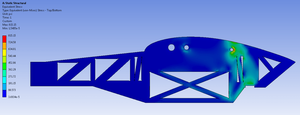
Finite Element Analysis The use of finite element analysis was critical for ensuring that a worst case landing wouldn’t destroy the plane. This analysis was conducted using ANSYS workbench. The worst case scenario was determined to be approximately 5 times the weight of the fully loaded plane directly on the rear wheels. Considering the effect of the worst case scenario and strength properties of the Birchwood a factor of safety of approximately 5 was achieved and deemed more than sufficient. Another evaluation with a load split between the rear and front landing gears was also done, but reduced overall impact, increasing the factor of safety to 7.
Thermal Analysis Thermal effects from the engine and exhaust components can be impactful to the performance and to components of a plane. The heat from exhaust components specifically can ruin the surface finish of the monokote wrap. Because of this issue, the temperatures at the engine mounting point was taken when at full operation. The ambient temperature of the air surrounding the exhaust pipe, as well as the exhaust itself, was also taken. After these measurements, it was determined that the heat generation wasn’t sufficient to effect the wrap. The effects of the exhaust on lift production was also deemed negligible.
Minor Considerations
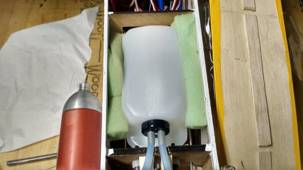
Foam inserts used for damping vibrations, mitigating air pockets in fuel.

Slot for cable routing. Needed for connecting radio systems, servos, camera cabling, etc.
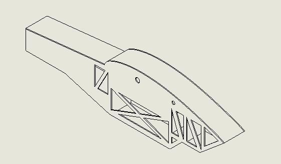
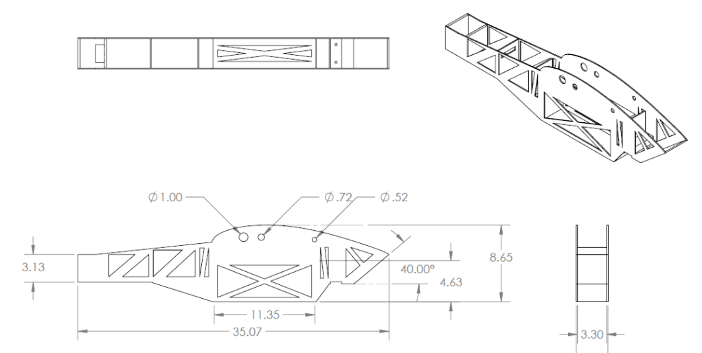
Final Design CAD

Manufacturing
The Fuselage was designed with the use of laser cutting in mind. This ensures complex wing geometries could be integrated seamlessly. Majority of components were cut to size in this manner. The ballast used were iron and cut to size using a milling machine, since the only a simple geometry was needed. The primary goal of the ballast is an exact weight for center of gravity adjustments. The assembly of fuselage was done using a combination of wood glue and cyanoacrylate. The attachment of the engine and landing gears were done using t-nuts to bite into the wood. Servos were secured using double side tape.

Results
The design was ultimately successful. The weight of the fuselage itself was increased in weight compared to prior years by approximately 0.2lbs, but with an improved design that reduced the need for ballast by over 2lbs, an overall reduction in weight of 1.8lbs was achieved. This was a weight reduction of 30% from the previous teams approach. Costs were also in line with expectations. Ultimately, our plane was successful in our competition, placing within the top 10 of competitors.
